Proposal Activities for Piping Engineering Scope.
Abhijit.S.Musale
www.abhijitsmusale.com | September 2025
Keywords
Piping
Project Proposal
Engineering Management
Cost and Efforts Estimation
Schedule
Deliverable List
Summary
The objective of this article is to present an overview of the piping-related activities undertaken during the proposal stage of a new project. It outlines how a project proposal is initiated and details the specific tasks associated with piping at this stage. The discussion includes the key contents of proposal documents, the methodology for estimating man-hours, resources, and costs within the piping engineering scope, and the process of preparing deliverable lists. Additionally, it explains how project schedules are determined, how kick-off meetings are conducted, and the principal topics addressed during these meetings. Finally, the article describes the steps involved in formally initiating the project.
Introduction
Developing a project proposal is a demanding and methodical process. At its core, the proposal aims to secure new work through competitive bidding, where several engineering firms present their solutions. Success depends on finding the right balance: the proposal must be priced competitively enough to win the contract, yet carefully structured to ensure profitability under varying market conditions. At the same time, it must demonstrate a commitment to quality, reliability, and safety in design. Pricing missteps can have significant consequences. An inflated estimate may result in losing the bid, while an undervalued proposal risks eroding margins and even causing financial losses. Because of these high stakes, proposals are prepared by professionals with deep expertise in their fields. Their experience allows them to recommend solutions that are both technically sound and economically viable, ensuring the company remains competitive while delivering value to the client.
The scale of a project often determines the number of engineering disciplines involved in proposal development. Different organizations use varying criteria to classify project size, which may include total manhours, overall cost, or the level of capital investment. Based on these and other factors, projects are typically categorized as small, medium, or large. Smaller projects may have a limited scope, sometimes requiring only a single discipline—for example, piping engineering—with workloads amounting to just a few hundred manhours. In contrast, larger projects encompass broader scopes and demand collaboration across multiple departments. These may involve disciplines such as electrical, civil, structural, architecture, mechanical, and instrumentation, each contributing specialized expertise to ensure the proposal addresses all technical and operational requirements.
Project proposals are typically overseen by a proposal manager, who is responsible for ensuring the final submission meets all requirements. This role involves close coordination with lead engineers or discipline heads across the various departments engaged in the project. Each lead provides inputs related to their specific scope of work, which the proposal manager consolidates into a comprehensive report. Effective proposal development also requires significant collaboration among discipline leads and their engineering teams. Through this collective effort, accurate estimates and well-structured proposal documents are produced, ensuring that the submission reflects both technical rigor and organizational capability.
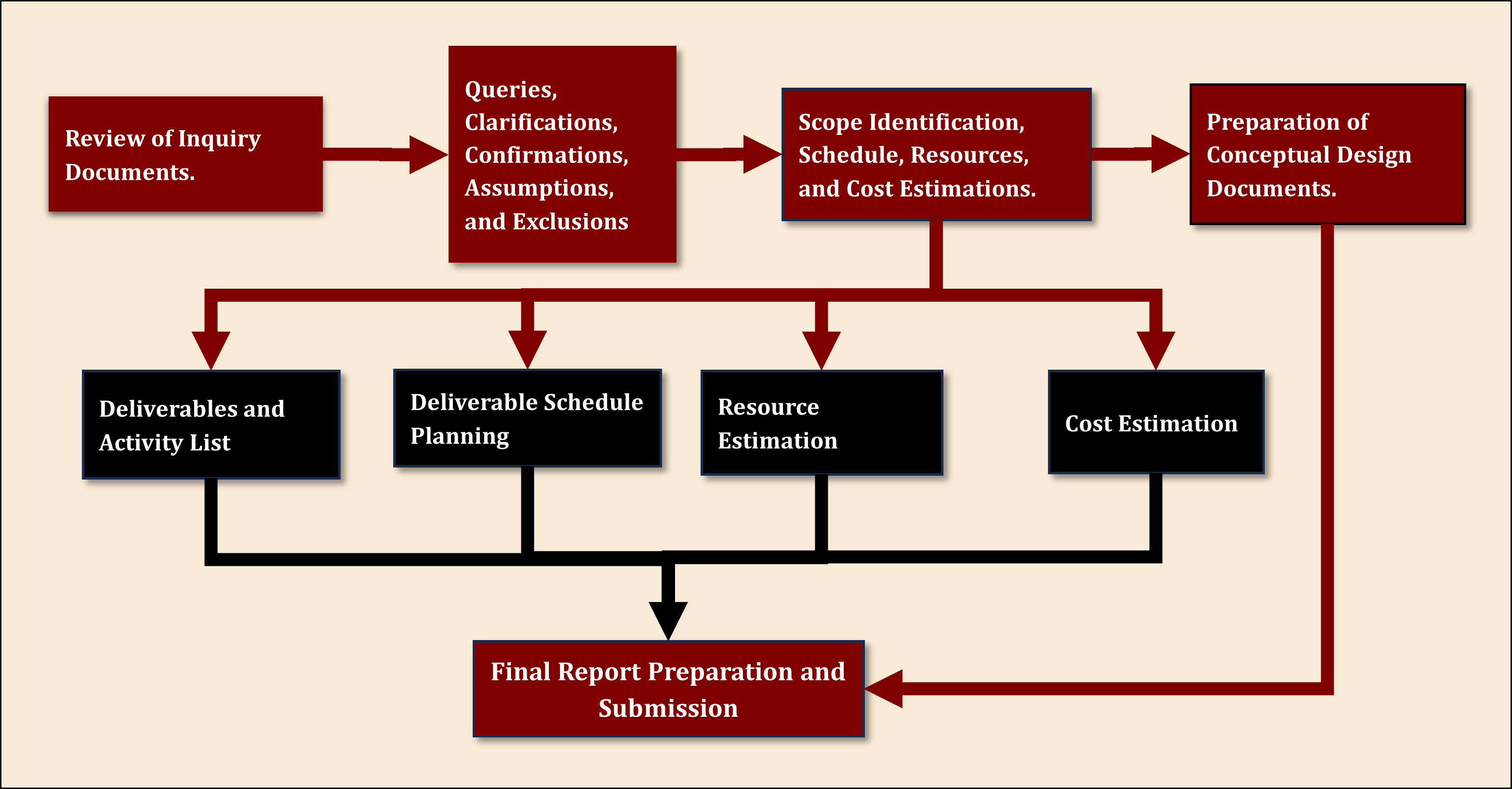
In this article, I will outline the key stages and activities involved in project proposal development, specifically from the perspective of piping engineering. The process follows a systematic sequence, where each stage contributes to building a comprehensive and competitive proposal. The flow diagram below illustrates these stages.
1. Technical Reviews, Queries, Deviations, Clarifications & Confirmations, Assumptions and Exclusions.
Process plants are owned by organizations that generate profits through the sale of products manufactured in these facilities. As their business expands over time, owners often face the need to either upgrade and expand existing plants or construct new ones to scale up production and sustain growth. These organizations, referred to as owners, engage engineering firms with the expertise to design such plants. Owners may approach engineering companies directly by issuing inquiries, or they may initiate an open bidding process, allowing multiple firms to submit proposals. The choice of approach depends on the scale and nature of the project.
For large or highly specialized projects, only a limited number of engineering firms possess the necessary capabilities. These firms are typically well known to the owners, and some are preferred based on prior experience or reputation. In such cases, owners issue invitations to bid exclusively to these selected firms. This process, restricted to invited participants, is known as a "closed bid".
Conversely, when the project scope is relatively small and the work can be executed by any competent engineering organization, owners issue an open invitation to bid. This allows all interested vendors to submit proposals, resulting in what is termed an "open bid".
In both scenarios, the submitted offers are reviewed by the owner's engineers. At times, owners may appoint independent engineering firms—known as Owner’s Engineers—to evaluate the bids on their behalf. These firms assess the proposals, compile their findings, and present recommendations in a formal bid evaluation report.
When inviting vendors to bid, owners provide extensive documentation outlining project requirements. These documents typically include an introduction to the project, its objectives, high-level requirements, location details, and information on parties involved if construction is already underway. They also describe the scope of work for which bids are solicited, the services expected from bidders, and any exclusions. In addition, discipline-specific documents may detail requirements for areas such as piping, civil, mechanical, or electrical engineering. Financial and legal documents are also provided, though they fall outside the scope of this discussion. Procedural documents specify the bidding process, required formats, submission guidelines, and deadlines. While many of these materials are not directly relevant to piping engineers, among them are documents that outline specific requirements for the piping discipline. These are the primary focus of interest for us.
Documents outlining the technical requirements are thoroughly reviewed by a competent engineer. Based on their expertise and professional judgment, the engineer evaluates the requirements described for the project. In some cases, the documentation may lack sufficient detail, contain inaccuracies, or include information that is not relevant to the project. It is the responsibility of the engineer to identify such gaps or discrepancies and raise appropriate queries and requests for clarification with the client. These queries are systematically recorded in a query register and communicated to the client for resolution. The client’s responses to these queries form an important basis for technical considerations in the project. Any ambiguous or incorrect information is formally addressed with the client to obtain clarification or correction. In instances where information is completely missing, the engineer may either directly request the required details or make reasonable assumptions, which are then submitted to the client for confirmation.
Sometimes the bidder takes deviations from the technical requirements that is specified by the client. Deviations refer to technical points where the bidder proposes solutions that differ from the client’s specified requirements. Such alternatives may be offered for several reasons. In some cases, the bidder’s solution fully satisfies the technical criteria but does not align exactly with the client’s stated approach. In other instances, the bidder may possess more advanced or updated solutions than those outlined in the client’s specifications. Cost‑effective alternatives that meet all technical requirements may also be recommended to optimize project expenditure. Every deviation is clearly documented, accompanied by a detailed justification, and included in the query list for transparency. When the number of deviations is significant, a separate deviation list is prepared to ensure clarity and submitted to the client for review, agreement, and formal consideration.
Assumptions are typically covered in the final proposal report. When specific information is not available in the inquiry documents and client also unable to provide the same at the proposal stage, then nessessary assumptions are made as per engineering practices of the organiztion. These assumptions are clearly documented and communicated to client. This compiled document serves as a critical reference for technical evaluation, supplementing the technical requirement documents provided by the client.
Exclusions are a list of services or deliverables that are deliberately excluded from the scope of work. Exclusions may be defined for several reasons—for instance, to avoid ambiguity, when the required capability is not available within the engineering organization, to maintain cost and schedule within agreed limits, or because the specific scope is assigned to another party. Could be any other reason. Such exclusions are clearly documented and communicated to the client for review, agreement, and consideration.
| Technical Reviews, Queries, Clarifications, Confirmations, Assumptions and Exclusions. | |
|---|---|
| Technical Review | It is a review of the inquiry documements by an engineer. It may include following documents. 1. Contract Documents. 2. Technical Requirement Documents. 3. Survay Reports, FEED Reports, Priliminary plot plan. 4. Technical Bulletines. Email communications from client. |
| Queries | Technical Queries are raised by engineers upon through review of the inquiry documents 1. Query register or Query list is prepared to document these queries. 2. Discripancies, missing, ambiguious and contradicting information identified and listed in query register. 3. Clarity regarding scope can also be requested in this list. |
| Deviations | Deviations are those technical points regarding which the bidder offers solutions other than what the client is requesting. An alternative solution. |
| Clarifications & Confirmations | Clarifications and confirmations are provided by client in response to query list. Clients may also provide their disagreements or non confirmations on cetain points. These client responses forms an important basis for technical considerations in project along with inquiry documents. |
| Assumptions | When certain information is unavailable at the proposal stage, and the client is unable to provide a confirmed response, engineering organizations make assumptions based on their expertise. These assumptions are formally communicated to the client, who then reviews and provides agreement or confirmation before the proposal proceeds. |
| Exclusions | It is a list of services or deliverables that are deliberately excluded from the scope of work. |
Scope Determination and Deliverable List
Once all documents have been reviewed and client queries have been addressed, the project scope definition is developed. The scope definition provides a comprehensive summary of the work required to successfully execute the project. Each engineering discipline prepares its own scope definition specific to its area of responsibility.
As this document is focused on piping engineering, only piping-related scopes are described here. The scope of work may vary depending on the project type and client requirements. For example, in brownfield projects where an existing plant is being modified or expanded, the scope may be limited to a specific section of the plant. In some cases, the client may require only selected deliverables rather than the complete engineering package.
| Piping Engineering Scope Definations | |
|---|---|
| By number of Piping Systems | The scope of work is defined by the piping systems or services included. In some cases, only specific systems are covered, while in others, all applicable piping systems are considered. These services are clearly listed in scope defination. |
| By Number of Pipe Counts | In some projects, the scope of work is defined by the number of pipe counts involved. Engineering services applicable to these perticular pipe lines are considered in scope. |
| By type and number of deliverables | The scope of work may also be defined by the type and number of deliverables requested by the client. For example, the client may specify only 3D modeling, isometric drawings, stress analysis, or material specifications—or any combination of these and other documents. |
For instance, a client may request only detailed engineering services, focusing on 3D model development using a specific software platform. In other scenarios, the requirement may include deliverables suitable for direct use in fabrication and construction, such as 3D models, isometric drawings, and Bills of Quantities (BOQs). For greenfield projects, the scope may encompass the full range of engineering activities, including basic engineering deliverables such as design basis documents, specifications, and engineering calculations, in addition to detailed engineering outputs.
Where the project scope includes procurement activities, additional tasks such as preparation of Requests for Quotation (RFQs), bid evaluations, and vendor coordination are also incorporated. Based on the specific project requirements, either a subset or the entirety of these activities and deliverables is defined.The scope definition clearly identifies the plant areas or piping systems included within the project, outlines the engineering and drafting services to be performed, and specifies the associated activities and deliverables. A separate deliverable list is prepared, detailing all documents and outputs to be submitted to the client. This deliverable list is reviewed by the client, who may suggest additions or deletions. It is subsequently refined through discussions and meetings until both parties reach mutual agreement prior to project commencement. Typical deliverables for piping engineering projects are listed below for reference.
| Types of Piping Engineering Deliverables | |||
|---|---|---|---|
| Documents | Quantities | Time Estimates | Notes / Remarks |
| Design Basis Documents | Each one document per project. | Seven to ten days each. (60 to 90 Hours) |
They are key documents for piping engineering work. They contain the basis of all the piping engineering related work. They contain design basis for piping layout, Material and Stress analysis. These Documents are prepared at the begining of the project. In case of brownfield projects these documents may already exists and are provided by client. Key Documents are 1. Piping (Layout) Design Basis Document. 2. Piping Stress Analysis Design Basis Document. |
| Pipe and Valve Material Specifications / Classes / Datasheets | Each One Document per Project | Ten to twenty days. Depending on the varity and quantity of material classes and valve datasheets involved. (90 to 180 Hours) |
Provides complete information regarding the material used for piping in project. Contains multiple material classes and valve data sheet depending on the process parameters and material of the pipes considered in the project. It is essential document to start modeling work to input right material data in 3D invironment. This has great impact on BOQ generation during last stages of project. Needs to be available or prepared at the beginning of the project. In case of brownfield project this document may already exist and is usually provided by client. Key Documents are: 1. Pipe Material Specification 2. Valve Material Specification |
| Piping Calculations. | Multiple Calculations as listed in the Remark column. Few or all of them need to be considered as per agreed scope of project work. | Depending on the calculations and the extent of it, different amount of time is estimated for each of the calculation deliverables. Approximate time required has been mentioned against each of the documents in the remark column. |
Piping calculations are at the core of engineering work. These calculations provide basis for sizing and selection of every aspect of piping. almost all of the documents depends on the results of these calculations. Key Documents are: 1. Pipe Sizing and Pressure Drop Calculations. (Depending on the piping system size and the number of flow streams involved it could take anywhere between 7 to 20 days. Depends heavyly on the data from process simulation. Normally these calculations are done by process department but sometimes the pipe sizing scope for simple systems (Non chemical reaction services) also assigned to piping department.) 2. Piping Thickness Calculations. (Relatively simple calculation. Standard excels sheets are kept with every organizations, mostly made by them selves, or there could be some software tool, in which you put the parameters and the tool tells you what thickness of pipe you should consider for your piping services. This does not take more than 2 to 3 days. ) 4. Miter Bend Calculations. (Can be prepared within a day but considering some time for checking, commenting, and correcting it would not take more than 2 days. ) 5. Branch Reinforcement Pad Calculations. (Another simple calculation, No more then 2 days.) 6. Pipe Rack width Calculations. (2 days approx. The thing about piperack witdth calculations is that it keeps updating in the initial phase of the projects. It depends hevyly on the pipe sizing calculations. One size change in any one of the pipes could impact the pipe rack width.) 7. Pipe Stress Analysis Related Calculations. (Each stress analysis calculation report takes around 6 days to 10 days if the piping system involved is relatively simple to analyze. For larger and more critical systems I have seen people working on just one stress calculation for weeks.) Pipe Stress analysis itself is collection of other sub calculations, such as wind load calculations, snow load calculations, seismic load calculations, Nozzle load calculations, Nozzle displacement calculations... so on and so forth... but they are all collectively considered within stress analysis calculations. No separate man hours are considered for them. |
| Piping 3D Modeling | Exact quantity of the pipes that need to be modelled is determined based on the PIDs, or line lists prepared by the process department. Number of lines could be in few hundreds or could be in thousands depending on the project size. Exact number of lines forms the basis on which the major part of effort and cost estimation depends. So, Number of lines is very inportant information for scope definations. | For estimation purposes, as a thumbrule, it is considered that it takes approximately 4 hours for a skilled designer to model one pipe line. One Pipe line means one pipe line tag in line list. so, to get to the total hours, simply multiply four hours with number of line tags. That number is your total hours required to model all the piping in 3D environment. |
3D modeling work consists of various activities. 1. Creating the material specifications in 3D environment as per paper spec. This activity is done by the software admin. This activity is done once in the beginning of the project. 2. 3D modeling of the piping. 3. Consistency checking with the PID. 4. Clash detection and resolution. 5. Model review with internal and external stackholders. 6. Co-ordination with other engineering disciplines and their 3D models. 7. Comment incorporation of model review. 8. Final checking and review process according to checklist and incorporation of comments. |
| Equipment 3D Modeling | Quantity of Equipment to be modeled can be determined from the equipment list. Equipment list can be generated from the PIDs. Process department provides generates this equipment list. | The time required to model equipment varies depending on its size and the level of detail (LOD) involved. Modeling a single piece of equipment may take anywhere from 2 to 4 days. Smaller, less complex items—such as standard pumps—can typically be completed within a day, whereas larger and more intricate equipment, such as a steam turbine condenser with numerous nozzles, may require up to a week. The overall effort also depends on the number of unique equipment models required. Standby or redundant units are generally duplicates of the primary equipment, meaning that modeling five or ten identical pumps requires the same effort as modeling just one. | Most of the activities applicable for piping 3D modelling as mentioned above, also applies for 3D modelling equipments. |
| Piping Isometrics | Quantity of isometric drawings are same as the quantities of lines in line list. One isometric drawings may have multiple sheets. | For estimations purposes 4 to 5 hours per isometric drawing is considered. Total hours can be derived from multiplying number of lines with these hours. |
Activitites for piping isometric drawings are as folloiwng. 1. Extraction of isometrics drawings. 2. Proper anotation or some editing if required before checking. 3. Self checking by designer. 4. Checking and reviewing by piping engineer. 5. Comment incorporation of comments provided by engineer. 6. Final issue to client. |
| Piping GA drawings | The number of piping GA (General Arrangement) drawings depends on the overall plot plan and the piping layout. Unlike isometrics, GA drawings are prepared to scale, and their number can be significant when the plot area is large. Typically, the overall area is divided into segments, with each segment represented by one GA drawing. Within a segment, multiple layers of piping may exist, sometimes requiring additional GA drawings. The planning of GA drawings is often documented on the plot plan itself, with clear markings that indicate the location and coverage of each drawing. | For estimation purposes, approximately 3 to 5 days are typically considered for each piping GA (General Arrangement) drawing. The actual duration may vary depending on the complexity of the piping within the area and the number of section views required. In more intricate layouts, the time may increase, while simpler arrangements may reduce the effort needed. | Preparation of piping GA (General Arrangement) drawings involves activities similar to those required for piping isometric drawings. However, the checklists used for GA drawings differ in certain aspects from those applied to isometrics. Since the activities related to piping isometrics have already been described above, they are not repeated here. |
| Specifications, RFQs, BERs and VDRs for Speciality Items and inline piping components. | The number of specifications, RFQs (Requests for Quotation), BERs (Bid Evaluation Reports), and VDRs (Vendor Document Review) depends on the procurement packages included within the project scope. In some cases, only specifications are required, while other procurement-related documents may not be necessary. However, when procurement activities are part of the scope, the full set of associated documents must be considered during estimation. These procurement packages may cover equipment, piping components, and inline items, each contributing to the overall documentation effort. | Making specificaitons could take 5 to 10 days. Bid evaluation report could take 15 to 50 days depending on the type of package and number of bids being evaluated. Vendor Document Review could take 4 to 5 days for each vendor package. |
Procurement related scope may involve following activities. 1. Making specifications and datasheets according to sizing calculations. 2. Making RFQs. 3. Evaluating various bids received from Vendors and make a bid evaluation reports. 4. Conduct clarification meetings with vendors. Respond to their queries. Get their clarifications regarding deviations and non confirmities. 5. Once the PO is awarded, review vendors documents. Ensure their compliance with the agreed specifications. Follow them up for the delivery deadlines. 6. Negotiate with them for the change of quantities if the same is revised by the engineering team. Following are some examples of Mechanical and Piping Engineering procurement packages. 1. Rotory equipment packages such as Pumps, compressors, turbines, fans, etc... 2. Static equipment packages such as tanks, vessals, reactors, heat exchangers, condensers, cooling towwers, etc... 3. Metallic and non metallic piping components such as pipes, fittings, flanges, valves, nut bolts, gaskets, etc... 4. Other piping inline components such as strainers, steam traps, insulations, heat tracing, silencers, sight glasses, etc... Each of the items mentioned in above four points is separate procurement packages. There is separate BOQs for each of the items. Effort need to be estimated for each of the packages. |
| Piping Stress Analysis Reports | Quantities of piping stress analysis reports depends on the the number of stress critical lines or systems (Pipe systems that need to be stress analysed). The stress critical systems are identified based on the criteria mentioned in the piping stress analysis design basis documents. Each stress critical systems need to be analysed separately and needs separate stress analysis report. | Depending on the complexity of the stress system the stress analysis and complete report generation, its checking and review, and its final issue to client could take 7 to 20 days. As per experience from my other colleagues, it may take even more than that if the system is very large and complex. | I have written separate blog article "Piping Stress Analysis Workflow" on the stress analysis related activities. However to give brief Idea I am giving short list here. In depth details can be found in the article. Stress analysis Involves activities such as... 1. Input and data gathring. 2. Identification of stress critical lines and piping systems. 3. Making 3D model in the stress analysis software such as CAESAR II. 4. Performing stress analysis and bring the piping system within acceptable stress values by providing proper supports and recommending alternative pipe routing. 5. Perform required manual calculations. 6. Prepare the stress analysis report and stress markups. 7. Communicate with designers and engineering teams regarding the changes in pipe routing. 8. Review and comment stress analysis report. 9. Comment Incorporation. 10. Final Checking and Issue to client. |
| Piping Support Drawings. | The number of piping support drawings depends on the quantity of special supports required across the piping systems. In most cases, pipes are assigned standard support types with conventional arrangements. However, in certain layout situations, standard supports are not feasible, and special support arrangements must be provided. For estimation purposes, it is common to assume 1 or 2 special supports per stress system. Separate drawings are then prepared for each of these special supports. | For estimation purposes 2 to 3 days per special support drawing considered. | The location of special supports is typically determined by the stress engineer once the stress analysis is complete. In addition to analyzing loads and stresses, the engineer must also consider the actual plant layout to verify whether suitable steel structures are available for standard supports. When no feasible location exists for a standard support, a special steel arrangement must be planned. In such cases, the stress engineer provides sketches and stress markups to guide the designers. Based on this input, designers prepare detailed drawings of the special support arrangements using 2D drafting software such as AutoCAD. |
Schedule Planning
Scheduling and planning begin once all required documents have been received, the deliverables list has been established, and the review scope has been agreed upon and finalized. Based on this finalized deliverables list, a detailed schedule must be developed. This schedule defines when each document is to be delivered to the client and outlines the sequence in which the deliverables will be prepared. The sequencing of deliverables is critical, as it determines which documents are prepared first and which follow subsequently. Typically, deliverables are organized into logical groups and aligned with the overall project schedule. While the project may have a broader timeline, piping engineering deliverables are usually required within a specific, narrower schedule window. The project manager provides the project start date and an estimated duration, within which all deliverables must be planned and completed.
Another important aspect is the time required to prepare each deliverable. This duration can vary depending on factors such as company standards, engineering practices, project type, workforce skill level, and productivity. In many organizations, standard preparation times are predefined for different deliverables. For example, a piping design basis may require approximately seven days for initial preparation, two days for review, and one day for incorporating comments—resulting in a total of about ten days to issue the first revision.
For other deliverables, similar time estimates are either predefined or determined by engineers based on their experience and judgment when standard timelines are not available. These durations are typically presented as approximate ranges, which may vary depending on project complexity, industry, and organizational practices.
Using this information, a comprehensive schedule is prepared in which each deliverable is assigned a start date, due date, and delivery deadline. Dependencies between documents must also be considered. Certain deliverables cannot begin until others have reached a specific stage of completion. For instance, isometric drawings cannot be extracted until the 3D model has achieved the required level of maturity.
It is essential to ensure that all necessary input data is available at the start date of each deliverable. Some activities may be executed in parallel, provided sufficient resources are assigned. Proper resource allocation is therefore important to maintain workflow efficiency. Additionally, key project milestones, including start and completion dates, should be clearly defined within the schedule.
Resource and Cost Estimation
Resource planning and estimation are critical components of proposal activities. Broadly, resources can be classified into two main categories: human resources and physical resources. Human resources refer to manpower requirements, including the personnel needed to execute the project effectively. This includes evaluating the number of engineers, designers, and support staff required, along with their skill levels and expertise.
Physical resources, on the other hand, encompass all tangible and supporting elements necessary to complete the work within the defined timeline. These include tools, software, equipment, and other infrastructure requirements. In some cases, additional provisions such as dedicated office space may also be required depending on the project scope and client requirements.
In summary, effective resource planning involves a clear understanding of both manpower and physical resource needs. Each of these resource categories will be analyzed in detail in the subsequent sections. As described in the previous sections, manpower estimation is a critical component of proposal activities. Once the list of deliverables and the overall schedule have been established, there is sufficient clarity regarding the number of deliverables and the time required to prepare, review, and deliver each of them. Based on this information, the total number of hours required to complete all piping engineering deliverables can be determined. Table 4 below shows the example of the manhour estimation sheet. This table is only for the illustration purposes, the real manhour estimation table could be far more elaborative. Manhours mentioned in the columns B, C, and D are estimated hour required to prepare each of the document for preparer, reviewer, and approver. The last total in the last column shows the total hours required to complete the piping scope.
| Types of Piping Engineering Deliverables | |||||||||
|---|---|---|---|---|---|---|---|---|---|
| Document | Estimated MH per One Document | TOTAL | Quantity of Documents |
TOTAL Estimated Manhours |
|||||
| Preparer | Reviewer | Approver | |||||||
| MH | Grade | MH | Grade | MH | Grade | ||||
| A | B | C | D | E | F | G | H (= B + D + F) |
I | J (= F x E) |
| Piping Design Basis Document | 54 | E2 | 18 | E3 | 4 | M2 | 76 | 1 | 76 |
| Stress Analysis Design Basis Document | 54 | E2 | 27 | E3 | 4 | M2 | 85 | 1 | 85 |
| Piping Material Specification | 90 | E1 | 36 | E2 | 9 | M2 | 135 | 1 | 135 |
| Valve Material Specification | 90 | E1 | 36 | E2 | 9 | M2 | 135 | 1 | 135 |
| Pipe sizing and pressure drop calculation | 45 | E2 | 18 | E3 | 9 | M2 | 72 | 5 | 360 |
| Other Piping related Calculations | 45 | E2 | 18 | E3 | 9 | M2 | 72 | 5 | 360 |
| 3D Modelling (Equipment) | 9 | D1 | 4 | E2 | 2 | M2 | 15 | 10 | 150 |
| 3D Modelling (Piping) | 6 | D1 | 3 | E2 | 1 | M2 | 10 | 50 | 500 |
| Piping Isometrics Drawings | 4 | D1 | 2 | E2 | 0.5 | M2 | 6.5 | 50 | 325 |
| Piping GA Drawings | 18 | D2 | 4 | E2 | 1 | M2 | 23 | 10 | 230 |
| Stress Analysis Reports | 63 | E2 | 18 | E3 | 9 | M2 | 90 | 5 | 450 |
| Piping Support Drawings | 18 | D1 | 4 | E1 | 1 | M2 | 23 | 10 | 230 |
| TOTAL (1 to 12) | 496 | 188 | 58 | 3036 | |||||
| Note : The table contains dummy data provided solely for illustrative purposes. | |||||||||
Each deliverable typically involves multiple roles, including engineers, draftsmen, checkers, reviewers, and approvers. Each of these roles carries a different billing rate or manpower cost. For example, 3D modeling and drawing preparation are generally performed by draftsmen, whose hourly rate differs from that of an engineer responsible for checking documents and models. Similarly, engineering managers who supervise and guide the team have a higher rate, and final approvers—responsible for ensuring compliance with quality procedures and technical accuracy—also have a distinct cost structure. Based on the project schedule, the time allocation for each deliverable is known. These hours are further distributed across different activities such as preparation, checking, reviewing, and approval. Typically, the majority of hours are allocated to preparation, with smaller portions assigned to checking, reviewing, and final approval. This enables a clear understanding of how many hours are required for each role involved in the process.
The hours corresponding to each resource grade are recorded separately and in detail, typically within an Excel sheet for each deliverable. These entries are then subtotaled and consolidated to determine the overall manpower requirement. Table 5 illustrates an example of the hourly rate card for various employee grades. As shown in Table 4, the preparation of any single document involves multiple grades of employees for drafting, checking, and reviewing. The cost of document preparation is calculated by multiplying the estimated hours for each document with the corresponding hourly rate of employee grades, thereby arriving at the total cost of preparing each deliverable.
| Employee types | Employee Grades | Hourly Rates per Employee Grades. |
|---|---|---|
| Designers / Technicians | D1 | ₹ 100/hr. |
| D2 | ₹ 160/hr. | |
| D3 | ₹ 270/hr. | |
| Engineers / Subject Matter Experts | E1 | ₹ 150/hr. |
| E2 | ₹ 300/hr. | |
| E3 | ₹ 390/hr. | |
| Managers / Leaders | M1 | ₹ 320/hr |
| M2 | ₹ 610/hr | |
| M3 | ₹ 1100/hr | |
| Note : The grades and hourly rates shown are dummy figures for example purposes. The actual framework could be far more extensive and diversified. | ||
Once the list of deliverables and the project schedule have been finalized, along with cost estimates and required man-hours, the next critical step is resource onboarding. During the estimation phase, the exact personnel who will execute the work may not yet be identified; often, only the required roles or grades are defined. Therefore, resource planning becomes a key activity in project execution.
Based on the scope of work and the estimated effort, it is necessary to identify and assign suitable personnel. These resources may be sourced either internally from within the organization or externally through hiring. When an organization has sufficient capacity and a relatively lower workload, internal resources are typically allocated to new projects. However, during periods of high workload, internal availability may be limited, necessitating the recruitment of additional resources from external sources.
In project management terminology, personnel are often referred to as “resources.” When a company experiences a surge in project demand, additional resources may be hired permanently or engaged on a contractual basis, depending on project duration and long-term workload forecasts. Effective resource planning requires experience and foresight, including an understanding of the organization’s project pipeline and anticipated workload over the coming months and years. This enables better planning for workforce allocation and hiring strategies.
In addition to human resources, projects also require physical and tangible resources, which must be planned and arranged during the proposal stage. These include software tools, licenses, and IT infrastructure necessary for project execution. Common tools include general office software such as Microsoft Office, as well as specialized engineering software for disciplines such as structural, civil, electrical, mechanical, and piping design. Advanced 3D modeling tools—such as AutoCAD Plant 3D, PDMS, and similar platforms—are often required and can be expensive. These are typically procured by the organization’s IT department from authorized vendors. During the proposal phase, it is essential to assess whether the required software licenses are already available or need to be acquired, and to initiate procurement processes accordingly.
Certain projects may also require dedicated office space due to confidentiality requirements. In such cases, clients may mandate that only authorized personnel assigned to the project have access to specific work areas. These secure zones are typically controlled through restricted access systems, such as specialized access cards, to ensure data protection and confidentiality for sensitive projects.
Furthermore, standard office infrastructure—including workstations, laptops, desks, chairs, servers, and networking equipment—must be considered as part of resource planning. While organizations generally maintain baseline infrastructure, additional capacity may be required for larger projects or when scaling up the workforce. All such requirements must be anticipated and planned during the proposal stage to ensure seamless project execution. In summary, both human and physical resource planning are critical components of project preparation and must be addressed comprehensively during the proposal phase to ensure successful project delivery.
Preparation of Conceptual Design Documents
One of the most important activities in any proposal is the preparation of conceptual design documents. When a client issues a request for proposal (RFP), they typically expect not only commercial and technical submissions but also preliminary deliverables that demonstrate possible approaches to project execution. These early-stage documents provide high-level insights into how the project can be implemented and allow the client to evaluate different options.
At this stage, clients generally expect two or three alternative concepts. These may include variations in plot plan arrangements, plant layouts, or process configurations. For example, when developing a plot plan, multiple layout options may be proposed to position equipment, buildings, and utilities in different configurations. Each option reflects distinct considerations such as operational efficiency, safety, accessibility, and cost. The client can then review these alternatives and select the most suitable arrangement.
Similarly, process design may offer flexibility. Certain processes can be executed in multiple ways, depending on factors such as capacity requirements, efficiency targets, and budget constraints. In some cases, additional equipment may be included to improve throughput or reliability, while in others, equipment may be minimized to reduce capital costs. These variations are presented as part of the conceptual design, allowing the client to assess trade-offs between performance and cost.
The preparation of conceptual design documents is often one of the most extensive and resource-intensive activities during the proposal phase. Typical deliverables include multiple plot plan options, high-level Process Flow Diagrams (PFDs), and preliminary Piping and Instrumentation Diagrams (P&IDs). In addition, basic specifications for major equipment are developed, and key pipeline routings are outlined within the layout. Approximate Bills of Quantities (BOQs) and preliminary cost estimates are also generated based on the proposed concepts.
Given the breadth of work involved, a dedicated team of engineers and designers is required to develop these documents. Specialists from various disciplines collaborate to prepare drawings, perform initial sizing calculations, and develop conceptual models. Depending on the size and complexity of the project, this effort may take anywhere from a few weeks to two or three months.
In many cases, the client explicitly specifies the list of documents required as part of the proposal submission. These typically include plot plan options, PFDs, P&IDs, major equipment specifications, sizing calculations, and estimated BOQs. All deliverables are prepared with clear identification of alternative options—such as Option 1, Option 2, and Option 3—to facilitate evaluation by the client.
Upon submission, the client reviews the proposed options and selects the most appropriate one before proceeding further with the project. In some instances, the client may also compare submissions from multiple bidders and may prefer an option proposed by another party if it better meets their requirements. This competitive evaluation underscores the importance of well-prepared, technically sound, and cost-effective conceptual design documents during the proposal stage.
Preparation of Final Proposal Report
The Proposal Manager is responsible for preparing the final proposal report, which serves as the comprehensive and consolidated submission to the client in response to the Request for Proposal (RFP). This document brings together inputs from all engineering disciplines into a single, cohesive package.
Each discipline contributes its respective scope of work, schedule, cost estimates, deliverable lists, and preliminary conceptual design documents. These individual inputs are systematically integrated to form a unified proposal. All scope descriptions are consolidated into a single, clearly defined statement of work. Similarly, individual discipline schedules are merged into an overall master schedule, while deliverables are compiled into a comprehensive master deliverables list. Conceptual design documents—including drawings, diagrams, and layout options—are organized and included as appendices, typically categorized by alternatives such as Option 1, Option 2, and Option 3. This structured presentation enables the client to review and compare different design approaches efficiently.
A critical aspect of final proposal preparation is ensuring complete alignment and consistency across all disciplines. Interdisciplinary coordination is essential to verify that assumptions, data, schedules, and design approaches are fully synchronized. Any discrepancies can impact the credibility and feasibility of the proposal. In summary, the final proposal report represents a well-coordinated, multidisciplinary effort and serves as the definitive submission to the client, demonstrating both technical capability and organizational alignment.